Log In Register


Puckdropper has scored 289 goals and 351 assists in his lifetime.


Walthers GP9 Wheel Cleaning

Yesterday, I picked up a Walthers GP9M locomotive in the Wisconsin Central scheme. When I placed it on the layout and turned on the power, nothing happened. So, I gave it a gentle nudge to make sure it wasn't on a section of dirty track. Still nothing.

Immediately I suspected dirty wheels, and took a look at them. They were black, like someone had tried to use a "darkening" solution on the wheels.

So, in order to get this locomotive to run, I was going to have to clean the wheels. First, I connected a 9V battery to the motor terminals to get the wheels to turn. Then, I used a paper towel with cleaning solution to remove the topmost layer of gunk. That helped a little bit, the locomotive would at least move a little.

Next, I tried a dremel tool with polishing bit. Using the white buffing compound, I cleaned more of the gunk off the wheels. After 30 seconds or so, I had to stop and clean off the polishing bit. This usually works for the heavier cases of crud and dirt, and it did work here, but not good enough. The locomotive would move back and forth at high speeds, with the headlight flickering the whole time.

Finally, I switched to the steel wire wheel attachment on the dremel. This removed the rest of the gunk, and got in to the most important places on the wheel: Near the flange. A model railroad wheel tends to pick up power from around the center of the wheel tread in to the flange, and that's the point where it needs to clean most. The wire wheel successfully cleaned off the rest of the gunk, and restored a shining appearance to the wheel treads. When I tested it on the layout this time, the locomotive would crawl at low speeds like the one I installed a decoder in.

I hope the steel wheel did not remove any electroplated protective covering on the wheels. If it did, there may be issues in the future with dirty wheels.

Update: I've found a better way to clean the wheels than using a metal wheel. It's the Dremel 423E cloth polishing wheel.


Bachmann F unit decoder installation

Bachmann standard series diesels have use the same motor drive with many different shells. Some more modern locomotives have circuit boards for lighting and transfering power from the front to rear. This locomotive contains such a circuit board, but it is a homemade copy containing a White LED headlight circuit. (This circuit was printed in the April 2000 issue of Model Railroader.) The unit also has wires to connect to other locomotives to share the power picked up from the rails. These installation pictures are to show the flexibility of the T1 decoder.

Installation consists of breaking the traces to the headlight circuitry, disconnecting the motor from track pickups, and connecting the decoder according to the instructions.

The "quiet drive" feature of the T1 decoder quiets the noisy motor, and the Rule 17 headlight feature allows the headlight to dim appropriately.


Pic 1: Before decoder installation


Pic 2: Trimmed harness


Pic 3: Finished installation

Note: These pictures have been submitted to TCS for use on their webpage. If they wish to use them, that's great!

This post has been edited at 2008-01-28 19:56:10


MRC F7B decoder installation


Pic 1: Standard wiring

The first step in installing the TCS T1 decoder in this locomotive is to ignore the circuit board's designated "Red" and "Black". They are reversed. Also, note that "Gray" is spelled "Glay".

Other than that, installation is fairly straight forward. Connections are made by either soldering or using a plastic clip on the circuit board. The locomotives come with the clips in the box. If you don't have the clips, simply solder the wires to the board. As far as I can tell, the only thing soldering wires on to the circuit board does is keep them in place. (Except for the pickups from the rails.)


Pic 2: Determing Length


Pic 3: Trimmed harness

I like to keep my decoder wires as short as possible, so I don't wind up with a big mess. Pic 2 shows how I measure for the wire length. Simply overlay the harness where the decoder will go and where the wire will go. Cut the wire to approximately 1/4" larger than that distance. Pic 3 shows the trimmed wiring harness.


Pic 4: Testing on the layout

After everything's connected, give your locomotive a test. If it works, you're good to go!

Note: These images have been submitted to TCS for use on their webpage. If they wish to use them, great!

This post has been edited at 2008-01-28 19:51:56

This post has been edited at 2009-10-02 05:48:17


Walthers GP9M decoder installation

These series of pictures show how to install a TCS T1 decoder in a HO scale Walthers Trainline GP9M locomotive. This inexpensive locomotive was produced before DCC gained popularity, so the decoder has to be hard wired.

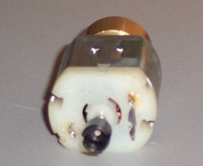
The first step in the process is to remove the weight bar and motor. Be sure to mark the motor to remind yourself which terminal is which. There's no distinguishing marks on this motor to indicate which terminal is which.


Pic 1 - Marked Motor

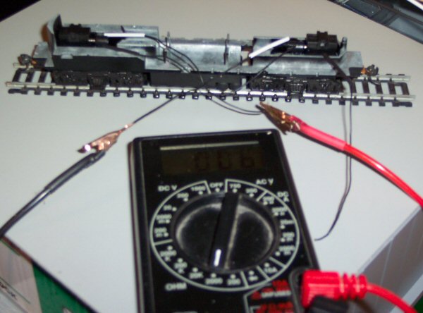
Next, since the pick up wires are both black, I used some heat shrink tubing to indicate which ones pick up from the right-hand (respective to the front of the engine) rail. I verified this by placing the locomotive on a piece of track and measuring the resistance with an ohm meter. A reading of close to 0 ohms means the wires connect.


Pic 2 - Pickups and multimeter

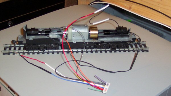
I followed the directions as to which wire went where, placing heat shrink tubing on any solder joints. After everything was connected, I then thought about where the decoder would mount. Big mistake. I should have thought of that first, as my initial mounting point would not allow the shell to be replaced on the
locomotive.


Pic 3 - Connected Wiring


Pic 4 - Initial decoder placement


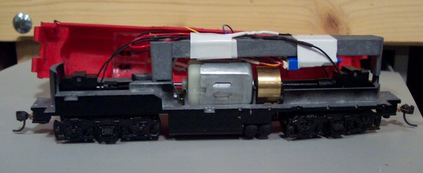
Pic 5 - Finished Installation, before shell is reinstalled

Notes:

1. All wire-to-wire solder joints were made using a "Western Union Splice." Simply overlap the exposed wire at the halfway point and twist the left wire around the right side, and the right wire around the left. This method makes a very smooth joint, allowing
heat shrink tubing to easily seal the joint.

2. Trim your wires, but leave at least an inch extra in case something goes wrong. I had a difficult time with making the motor power connection and wound up having to extend the orange wire.

3. These pictures have been submitted to TCS for use on their webpage. They're welcome to use them if they desire.

This post has been edited at 2008-01-28 19:34:04


My shoulder hurts, but at least my armpits are clean

I've been working on rewiring the layout... When I did the initial wiring, I used block wiring with a common wire. While that works well, my inevitable upgrade to DCC will be easier with both leads run back to the control panel.

So, dear reader, you're probably wondering what the subject's all about. Well, here's the thing: My terminal strip was installed behind the control panel, and I spent an hour or so under the layout moving wires around on it. The position I spent about half that time in was with my right hand raised above my head, and my nose facing my arm. Since I was also leaning on an under layout shelf, that started to make my shoulder hurt.

There's an important lesson to be learned in this, dear reader. When installing common wiring components, remember that eventually you'll have to work on them (that's the whole point of the terminal strip) and they should be mounted in such a way that working on them is easy on the body. If I had mounted my terminal strip on top of the control panel, and run the wires from underneath, I wouldn't be sitting here typing this post.


Some thoughts on wiring...

I keep messing with the wiring on my model railroad. It's not that it's bad, it's that it's not as portable as I'd like. When the railroad has to be moved, the wiring job isn't easy. Contrast this to Ntrak, where hundreds of modules can be connected together for just a single weekend. Each module, even those with the complex track plans, are connected and ready to go wiring wise in under 10 minutes a module.

A home layout, especially a block wired layout, presents different challenges, however. You no longer have a primary track bus to just snap together, you have wires for this track and that track. Even with as neat as I tried to be, I've still got a mess of wiring under the layout. As I go to redo it for the final time (I hope) I'm going to define and implement some conventions and standards.

Wires to the track will all trace back to a terminal strip on the module. They'll be a different color or style than wires that pass through the module. Wires that pass through a module will have PowerPole connectors on the ends, and since I don't have to worry about changing ends as a standards body does it, I can eliminate the two terminal strips per module required for the through bus.

Oh, did I mention in the next two years I expect to upgrade to DCC? This means heavier wire, which I have, and considering how the different blocks will tie together nicely. Does anyone make a European style distribution block?

As your layout gets more complex than a simple loop and siding, you need to sit down and seriously plan the wiring. If you're doing an incremental build, you still need to plan all the wiring first. This will save you many headaches later.


This post has been edited at 2008-01-09 06:19:15


The Benefit of Flux

I learned to solder at a very young age, and have kept doing so ever since. I've gone through a couple different soldering irons, but only last year discovered the benefits of using flux. For about $3 for a can, you can improve your soldering projects tremendously.

In soldering, heat transfer is key. If your don't get the joint heated properly, you'll never get a good solder connection. What the flux does is melt and transfer heat throughout your joint. When you touch the solder to this area, the solder will melt and transfer quickly and efficiently to where you want it. I've used flux on soldering rail joints, and other than perhaps cleaning the excess flux off, never had to do anything to the rail to run trains.

A little flux goes a long way, and be careful not to use too much. If soldering with an iron, you'll just wind up with a mess, but if soldering with a torch, that extra flux could burn and leave a nasty black residue.


Update to 0.6.1

Version 0.6.1
-----------

1. Fixed error in admin edit/delete page where wrong identifier was used.
2. Fixed error where name field is not filled in and the software rejects the post.
3. Fixed error where any unfilled in form values on postcomment.php complain the subject is blank.
4. Form values on postcomment.php do not blank out after errors.
5. Move included header file so no output occurs before redirect code in postcomment.php


It seems things don't go so well when you forget what you've tested. I think everything works now, if not, well, there's always 0.6.2.

This post has been edited at 2007-05-24 04:39:23


Laying Track Outdoors - Leveling and Ballasting

Leveling

After an unsatisfactory job with laying the track the first time, I took up the track (a loop around a gazebo) and started leveling the base out. I found that by mounding more gravel where the track had laid, in an area just a little taller than 3/4" and about the size of what fell off my shovel, I could tamp this down and get it level. Testing for level was done by using a piece of straight track in the straights and curves for curves. If I put the level on it, and it read level side-to-side, I went on. If not, I adjusted the gravel until it was level side-to-side. The track does not need to be level up and down (in the direction of movement), but MUST be level side-to-side.

Here's a tip: Use a piece of track and a quality combination square with level. Take the ruler section part off (and save the parts ;-)) and use just the head. This will sit nicely on sections of track you use to test for level.

Ballasting

Once the base was level, and the track installed again, I ballasted. I placed shovelfuls of the rock on top of the ties and tried to get it to sit down into the ties. I tried running a locomotive over the track to encourage the rock to settle, and that didn't work. The locomotive derailed before it got anywhere.

I then tried bringing out the snow plow. It's 80 degrees out, and the plow is working... Only on a model railroad, eh? Well, the plow succeded in pushing the bulk of the gravel out of the way that would interfere with the locomotive, but derailed several times itself. The track still didn't LOOK good, though.

After these failures, I decided to try the spray nozzle on the garden hose. This worked really well. By aiming the spray of water towards the rails (to push the rock away from it), I was able to convince the gravel to settle down into the area between the ties and blow most of the extra off. The track now looks decent, and is firmly held in place with the ballast.


Laying Track Outdoors - Posted to rec.models.railroad on May 16, 2007

It all started with an $8 purchase for a bunch of train stuff at a garage sale... Soon, I had a piece of track for my G-gauge locomotive as test track, and plans for a loop outside. To make a long story short, I'm skipping right to the laying track part.

Laying track for an outdoor railroad is a lot more prep work than that of an indoor layout. For an indoor layout, one merely has to attach track to a flat-ish surface and connect power. (Nitpick: Yes, quality track laying is much more difficult.) For an outdoor layout, "flat" is something that must be created. My simple loop of track required taking dirt out of the garden to level some of the worst spots, and tamping it all down.

Since things will grow in flat empty dirt, step two involves laying down a weed barrier and putting gravel on top of it. In my impatience to get trains running, I had laid track on top of the dirt and added the gravel later. I think this was a mistake. What I should have done was put the gravel down first, tamped it all down level, and then laid track. (G gauge track needs to be level side-to-side. Grades are fine, but you'll run into trouble with some equipment if it's not level side-to-side.)

If it's dry tomorrow (rained today) and I have the time, I'm looking at taking up the track, compacting the gravel underneath and leveling it side-to-side, and relaying it. It's a lot of work, but I think it's worth it.


Note: I posted this to rec.models.railroad on May 16, 2007.
Google Groups Archive


View next 10 entries

Home Creative Stuff Model Railroad Ice Rink Computers message board Site Updates