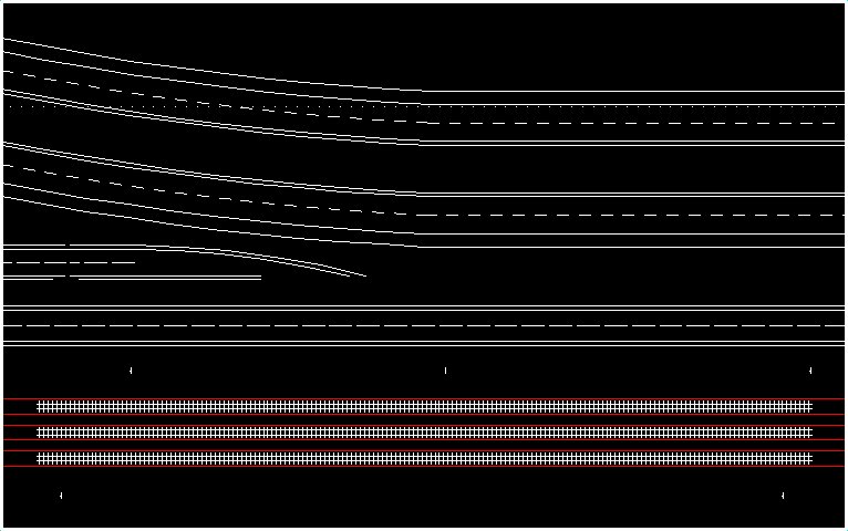
Puckdropper's Place Logo

Main Page | Pictures | Blog
DCC: GP9M Decoder Installation | JMRI on PowerPC
Construction: Painting Track | Module Construction | Module Design
New Stuff!: For Sale

Introduction

This page is designed to be the first of a series regarding building a Ntrak module from start to finish. In this article, I will describe the process used in the design of my latest module. While the series is based upon an Ntrak module, most of the techniques can easily be adapted to other scales and also used in your own layout design, modular or not.

Inspiration and Initial Design

I55, Rt. 66, and the Union Pacific
Throughout my life, I've often traveled on a stretch of Interstate 55 between Pontiac, Illinois and Dwight, Illinois. Running mostly parallel to I-55 is Historic US 66, and parallel to US 66 is the Union Pacific Mainline. When I think of Illinois, this is one of the areas that comes to mind.

The module design included need for artistic license to be taken. One significant change made was following the Ntrak specification of three main lines (actually it's two main lines and a branch line). My goal is not to model an exact scene, but one where a viewer feels like they know the area.

The initial design of the module consisted of reviewing the area I planned to model to get a solid idea of what I wanted to model. I traveled through the area on both US 66 and I-55 to learn how both roads go. Eventually I settled on one of the areas where I-55 curves to avoid a town and US 66 continues straight. This allowed me to model a unique feature of US 66: old sections of road that were closed but not removed.

Once I had decided what to model, I drew a couple sketches of what the module could look like. These sketches then guided my use of the computer aided design program.

Design

I usually use Atlas Right Track Software (RTS) (link) to design my track plans. However, the track plan for this module was very simple, and the elements that needed designed were beyond RTS's capabilities. This prompted a change from RTS to CadStd, a Computer Aided Drafing program. CadStd allowed me to design where I wanted the roads on the module to go with a minimal amount of fuss.

However, switching to CadStd (link) meant I would have to draw out the track myself, as well as the roads. As complicated as this sounds, drawing the track was easy. Track is a series of parallel and perpendicular lines. By drawing two parallel lines for the rails, then adding perpendicular lines for the ties, the track was quickly created. (By making the track representative, and not exact, I saved myself a lot of hassle.)

Aside: I have not tried curved track or turnouts at this time. For anything more complex than a simple curve, you'll probably want to use a model train layout design program.

With the track done, it was time to lay out the roads. Wikipedia had an article listing the interstate highway minimum standards (link). The article was the basis of my road width design plan. The Wikipedia article gave the dimensions in feet, but I needed scale actual inches. To get scale actual inches, I used this very simple formula:

Measurement divided by scale factor equals scaled measurement.


Where:
Measurement = measurement to scale.
Scale Factor = amount to scale. (In N, 1:160 scale, the scale factor is 160. In HO, 1:87 scale, the scale factor is 87.)
Scaled Measurement = scaled measurement. This has the same units as Measurement.

Therefore, 16 feet / 160 = 0.10 ft. Thus, to draw a 16 ft line in 1:160 scale, draw a line that is .10 ft, or 1.2 inches.

Roadway widths in feet and scaled actual inches.
Element Measurement Scaled Measurement
Ditch between rails and US66 40 ft 3 in
US66 Shoulder 3 ft 0.225 in
US66 East Lane 10 ft 0.75 in
US66 West Lane 10 ft 0.75 in
US66 Shoulder 3 ft 0.225 in
Ditch 45 ft 3.375 in
I55 Outside Shoulder 10 ft 0.75 in
I55 Northbound Lane 1 14 ft 1.05 in
I55 Northbound Lane 2 14 ft 1.05 in
I55 Inside Shoulder 4 ft 0.3 in
I55 Median 36 ft 2.7 in
I55 Inside Shoulder 4 ft 0.3 in
I55 Southbound Lane 1 14 ft 1.05 in
I55 Southbound Lane 2 14 ft 1.05 in
I55 Outside Shoulder 4 ft 0.3 in


Armed with the above table (well, not really... I've got a much less pretty one on notebook paper turned sideways,) it was time to lay out the roads. Most the elements of the road are parallel lines, so by laying out one element (usually the outside of the shoulder), it was a simple matter to create the rest of the road.

One place where the CAD program came in really helpful was in laying out I-55. The southbound lanes only fit part way on the standard 24 inch module. I could either attempt to give the illusion of those lanes in the backdrop, or expand the module width 6 inches for the scenery. I decided it would be better to expand the module width to accommodate I-55, rather than attempt to paint the lanes on the backdrop.

Another place where the CAD program helped was in allowing me to change the lay out of the roads. Initially, I had all the roads running parallel, with I-55 curving off on the north side. The final design had I-55 curving in from the south, with an original section of US 66 ending where I-55 comes in.

Final version of the module design.

Conclusion

While the module design has finished on paper, there are other factors I will have to consider in building the module. For example, digging out the required ditches would be much easier done in foam, but it's not a good idea to use foam alone for a portable module. Were I to use 2 inch foam insulation, I would make it more difficult for the module to be clamped to the next one. Another consideration is how to lay the track on the module. Should I lay the track on the foam itself, or lay a strip of plywood? Just because the design is done, doesn't mean all the decisions are made yet.

Links

Atlas Right Track Software
CadStd
Interstate Highway Standards - Wikipedia Article

Home Creative Stuff Model Railroad Ice Rink Computers message board Site Updates