Log In Register


Puckdropper has scored 287 goals and 347 assists in his lifetime.


Tip: Measure, then build smaller

When building a layout to fit between house walls, measure the distance between the walls at the point that sticks out the furthest (any trim, outlets, etc) and then build your layout slightly smaller. It might come down to modifying either your layout or the room to make it fit.


This post has been edited at 2008-10-13 02:21:26


Upgrade to Version 0.7!

Version 0.7
-----------

1. Colors are set by using define now, no longer by assigning values to global variables. (As a positive side effect, I deleted about 50 source lines.)
2. Added new color definition for warning messages.
3. Common user messages are stored in a single file.
4. Usernames are now stored unencrypted in the database.
5. Database access information is now stored in a seperate file. -- Repealed
6. New Feature! Installation.
7. Missing database is detected on the index page and an error message displayed.
8. New API functions! display_status_message($statustext) and display_error_message($errortext)
9. Rewrote index.php page to make the post selection and display functions much clearer. Also, the "View next X entries" and "View first X entries" behave a little more intelligently.
10. Added new option to decide how many messages to display on main page.
11. New Feature! Installation on a single database! (You will have to install the code in a new folder.)
12. Avoided stray capitol letters. Honestly, what's the deal with these case-sensitive languages?
13. Integrated in to web page. Basic direction is done via header, website navigation via footer.
14. Database access information now NOT stored in seperate file. Change #5 is repealed.
15. Blog version is stored in the database and updated with the database.
16. New Feature! Changable Options! (Right now, you can only change the number of messages displayed on the main page.)
17. Changed position of Goals Scored message. (A side effect of Version 0.6's login status code.)
18. New Feature! Record of goals scored!
19. Fixed security hole where one installation's login status transfered to anothers.
20. Fixed mistake where all radio buttons on the delete category page would have the "checked" property.


Expansion

I'm expanding my model railroad by replacing the old one with a new one. This time I'm doing things differently. The modular design is being replaced with a sectional design, the storage underneath is being made more useful, and some consideration is given to "human factors."

The previous layout was built with a modular design, with the goals of making it easily moved and able to be displayed at a train show. The layout never got finished enough to even consider displaying at a show, but it did make several moves easily. The new layout is still intended to be able to be moved from house to house, but it is not intended to be taken to shows. This means longer sections and fewer mechanical and electrical connections.

Storage underneath the previous layout consisted of a plywood shelf about midway between the floor and the underside of the layout. This simple shelf also braces the legs of the module. Unfortunately, the design of the shelf tends to lead to large boxes and other heavy, bulky items being placed on it. These items must be removed if access to the underside of the layout is required. The shelves are being replaced with "tool chest" style cabinets, where the cabinet consists of drawers inside of a larger box on casters. When access to the underside of the layout is needed, the cabinet can be rolled away.

Human factors are things external to the layout operation that make the layout more enjoyable. Aisle width, aesthetics, and an elbow/cup/tool rail are all human factors I've considered in the new layout. An aisle width of 3' is standard, with a few small locations that have less than that. Aesthetics have been considered with painting the benchwork. Rather than an unfinished wood, the benchwork should appear to disappear into a sea of gray. The focus will be on the layout itself, and not what's underneath. One of the other human factors considered was that of a cup rail. This is a railing around most the layout for cups, elbows, and tools, to try to keep them off the layout. Were it padded, it would provide a first line of defense in minimizing rolling stock damage.

There's more to a model railroad than just the track plan and scenery. Factors such as benchwork design, supplemental storage, and human factors can make a huge difference in how a layout turns out.


Upgrading to DCC

Upgrading to DCC

Recently, I upgraded my home layout to Digitrax DCC. The upgrade was easy, I had trains running after connecting power to the command station and connecting the track to the command station. Setting up a programming track was a little more difficult, as I wanted to use the programming track as a siding as well. All I had to do was connect the track and programming track outputs to a Double-pole Double-throw switch. Switching between siding and programming track mode is as simple as throwing the switch.

The block wiring remained largely untouched, and is still usable. There's no reason to remove it, but several to leave it in. Perhaps the most important reason is isolation is much easier. If a problem develops there's no feeders to remove or cut, simply throw a switch. Plus, if you decide to install circuit breakers, the blocks are already gapped and cut.

I got a little overzealous with wiring, and added a run out to my test track in the other room. This included the loconet wiring necessary for selecting and running locomotives. Loconet uses the same wiring as standard phone wiring, so 6 conductor phone wire and normal phone jacks are all that's necessary. (It's probably not a good idea to plug a telephone into a loconet jack or a throttle into a phone line.) I need to add a note on the main control panel as a reminder that an isolated track in another room is controlled by DCC.

Overall, the entire process was easy. If a model railroader is able to wire a layout with block wiring using conventional DC, they'll be able to connect a DCC system. Running trains is also easy, but programming is a little more difficult. All in all, it's a worthwhile upgrade.


Metal Wheels and Metal Weight

Some metal wheels have enough free play to touch metal weights located under the car. If this happens it could cause a short, or in some cases start a fire! To prevent this, cut a thin piece of styrene the size of the weight and install it between the wheels and weights. With most cars, this won't change your coupler height at all.


Sagging Couplers

I've recently been dealing with sagging couplers. Sometimes I can simply remount the coupler in the box, and everything's fine again, but other times I'm required to replace the sagging coupler all together. Some have suggested that shimming the end of the coupler can solve the problem, but I have had issues maintaining free movement when shimming with 0.010" styrene.

I like the "whisker" centering spring in many non-Kadee couplers, but usually wind up replacing them with Kadee couplers. The big advantage here is that they're all metal, and minor repairs are possible. Kadee's been advertising their whisker couplers in MR recently, so I might have to get a set.

If I get another manufacturer's couplers, such as McHenry, I'll give them a fair test before switching to Kadee. I'm not going to go out and buy a set just to try them out, though. I've been extremely happy with what I've got.

I'll say one thing positive about the cheap knuckle couplers: They are a 1000 time improvement upon the nasty horn-hooks. Horn-hooks should be banned from interchange traffic!


On an unrelated note, I'd like to thank the spammers for stress testing my blog software. I must say, 800 comments is WAY too many to display on one page. You'd get tired of reading long before you got to the last one.


Walthers GP9 Wheel Cleaning

Yesterday, I picked up a Walthers GP9M locomotive in the Wisconsin Central scheme. When I placed it on the layout and turned on the power, nothing happened. So, I gave it a gentle nudge to make sure it wasn't on a section of dirty track. Still nothing.

Immediately I suspected dirty wheels, and took a look at them. They were black, like someone had tried to use a "darkening" solution on the wheels.

So, in order to get this locomotive to run, I was going to have to clean the wheels. First, I connected a 9V battery to the motor terminals to get the wheels to turn. Then, I used a paper towel with cleaning solution to remove the topmost layer of gunk. That helped a little bit, the locomotive would at least move a little.

Next, I tried a dremel tool with polishing bit. Using the white buffing compound, I cleaned more of the gunk off the wheels. After 30 seconds or so, I had to stop and clean off the polishing bit. This usually works for the heavier cases of crud and dirt, and it did work here, but not good enough. The locomotive would move back and forth at high speeds, with the headlight flickering the whole time.

Finally, I switched to the steel wire wheel attachment on the dremel. This removed the rest of the gunk, and got in to the most important places on the wheel: Near the flange. A model railroad wheel tends to pick up power from around the center of the wheel tread in to the flange, and that's the point where it needs to clean most. The wire wheel successfully cleaned off the rest of the gunk, and restored a shining appearance to the wheel treads. When I tested it on the layout this time, the locomotive would crawl at low speeds like the one I installed a decoder in.

I hope the steel wheel did not remove any electroplated protective covering on the wheels. If it did, there may be issues in the future with dirty wheels.

Update: I've found a better way to clean the wheels than using a metal wheel. It's the Dremel 423E cloth polishing wheel.


Bachmann F unit decoder installation

Bachmann standard series diesels have use the same motor drive with many different shells. Some more modern locomotives have circuit boards for lighting and transfering power from the front to rear. This locomotive contains such a circuit board, but it is a homemade copy containing a White LED headlight circuit. (This circuit was printed in the April 2000 issue of Model Railroader.) The unit also has wires to connect to other locomotives to share the power picked up from the rails. These installation pictures are to show the flexibility of the T1 decoder.

Installation consists of breaking the traces to the headlight circuitry, disconnecting the motor from track pickups, and connecting the decoder according to the instructions.

The "quiet drive" feature of the T1 decoder quiets the noisy motor, and the Rule 17 headlight feature allows the headlight to dim appropriately.


Pic 1: Before decoder installation


Pic 2: Trimmed harness


Pic 3: Finished installation

Note: These pictures have been submitted to TCS for use on their webpage. If they wish to use them, that's great!

This post has been edited at 2008-01-28 19:56:10


MRC F7B decoder installation


Pic 1: Standard wiring

The first step in installing the TCS T1 decoder in this locomotive is to ignore the circuit board's designated "Red" and "Black". They are reversed. Also, note that "Gray" is spelled "Glay".

Other than that, installation is fairly straight forward. Connections are made by either soldering or using a plastic clip on the circuit board. The locomotives come with the clips in the box. If you don't have the clips, simply solder the wires to the board. As far as I can tell, the only thing soldering wires on to the circuit board does is keep them in place. (Except for the pickups from the rails.)


Pic 2: Determing Length


Pic 3: Trimmed harness

I like to keep my decoder wires as short as possible, so I don't wind up with a big mess. Pic 2 shows how I measure for the wire length. Simply overlay the harness where the decoder will go and where the wire will go. Cut the wire to approximately 1/4" larger than that distance. Pic 3 shows the trimmed wiring harness.


Pic 4: Testing on the layout

After everything's connected, give your locomotive a test. If it works, you're good to go!

Note: These images have been submitted to TCS for use on their webpage. If they wish to use them, great!

This post has been edited at 2008-01-28 19:51:56

This post has been edited at 2009-10-02 05:48:17


Walthers GP9M decoder installation

These series of pictures show how to install a TCS T1 decoder in a HO scale Walthers Trainline GP9M locomotive. This inexpensive locomotive was produced before DCC gained popularity, so the decoder has to be hard wired.

The first step in the process is to remove the weight bar and motor. Be sure to mark the motor to remind yourself which terminal is which. There's no distinguishing marks on this motor to indicate which terminal is which.
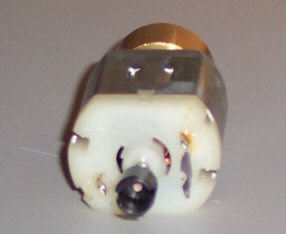

Pic 1 - Marked Motor

Next, since the pick up wires are both black, I used some heat shrink tubing to indicate which ones pick up from the right-hand (respective to the front of the engine) rail. I verified this by placing the locomotive on a piece of track and measuring the resistance with an ohm meter. A reading of close to 0 ohms means the wires connect.
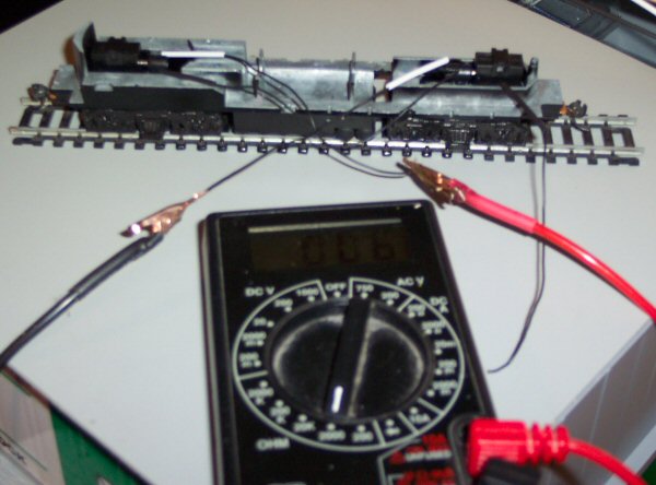

Pic 2 - Pickups and multimeter

I followed the directions as to which wire went where, placing heat shrink tubing on any solder joints. After everything was connected, I then thought about where the decoder would mount. Big mistake. I should have thought of that first, as my initial mounting point would not allow the shell to be replaced on the
locomotive.
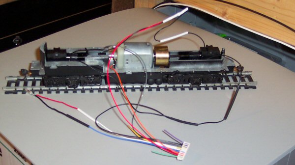

Pic 3 - Connected Wiring


Pic 4 - Initial decoder placement
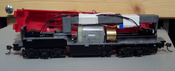

Pic 5 - Finished Installation, before shell is reinstalled

Notes:

1. All wire-to-wire solder joints were made using a "Western Union Splice." Simply overlap the exposed wire at the halfway point and twist the left wire around the right side, and the right wire around the left. This method makes a very smooth joint, allowing
heat shrink tubing to easily seal the joint.

2. Trim your wires, but leave at least an inch extra in case something goes wrong. I had a difficult time with making the motor power connection and wound up having to extend the orange wire.

3. These pictures have been submitted to TCS for use on their webpage. They're welcome to use them if they desire.

This post has been edited at 2008-01-28 19:34:04


View next 10 entries

Home Creative Stuff Model Railroad Ice Rink Computers message board Site Updates