Log In Register


Puckdropper has scored 283 goals and 341 assists in his lifetime.


A Minor Change

Since Ice Rink season is here, I'm going to shift my focus to building ice rinks. Eventually, I'll shift the ice rink blog over to the correct section.

Rink Experiments, Theory, and Building

Experiment 1: Camera
The sun has a direct bearing on the thickness of the ice. If the rink is shaded, I'll be able to skate longer without the sun melting the ice as quickly. In order to determine where to place the shade tarp, we need to know which areas the sun shines on most.

By utilizing a camera with a timer to take pictures several times an hour, we should be able to gather this data. A computer webcam and software is being used to take a photo every 5 minutes to observe the solar patterns. The data is being gathered as I type.

Experiment 2: Fencing
A temporary fence with fine enough graduations will prevent blowing snow and leaves from getting on the ice. A second benefit is pucks will be kept in. Think about a drift fence.

Experimental setup: Attach a fence to the rink boards and a second fence on the ground about 5-10' away. The second fence is to stop the majority of the drifts and leaves while the first will hopefully get the rest.

Replacing a Gear, Part IV

Sherline makes a single-point gear cutter for their mill. I've got a Taig mill, which uses a different setup in the spindle. This means I couldn't use the Sherline part, and I couldn't find one for the Taig. So, I built one.

I followed the Sherline design with a few key changes: I made the cutter with a 3/8" shaft so I could grip it in the Taig collet. Since I was making my gear out of Delrin, I used W1 tool steel instead of a HSS bit. The mill had no problem cutting the W1 (once I figured out speeds and feeds) and was used to put the correct profile on the tool. For reference, I put about a 5 degree relief on the tool so the back of the tool wouldn't cut as the tool spins.

Size caused a few issues trying to cut this gear. Since the holder was 1 1/2", and the tool bit stuck out about 1/2", there was a 2" diameter circle that had to be traversed freely in order for the tool to cut. This meant working at the end of a piece of 9mm Delrin, which resulted in lots of chatter. There wasn't enough room for the tailstock to support the work, so I had to turn a much longer center for the tailstock. Were I to do this over again, I'd try to keep the overall diameter of the cutter down to prevent this issue.

At the end, though, I had a pair of gear-shaped objects that ran together quite nicely. Not perfect, but enough to keep the process going.


More on Gears - Checking

When measuring a gear, there's only a couple things the average hobbyist can measure. One is the tooth count and the other is the overall OD of the gear. It's easy to get the tooth count wrong, so if you're looking to replace a gear here's a way to double check:

Calculate a probable tooth size (use a calculator or look up the formula.) Use the tooth size to calculate the pitch circle diameter (PCD) of the gear.

Using a CAD/3D modeling program or anything that will draw a gear and a circle, draw a circle of the overall diameter. Draw a gear of the tooth size and PCD and center it on the circle. The tips of the gear teeth should touch the circle.


Replacing a Gear, Part III

With the other attempts failing, I decided to try making the gear using a milling machine. I already had the file with the gear drawn, so simply used that. I decided 3 milling operations would be best: A rough pass with a large (1/8") endmill for the outside of the gear, a rough pass with a smaller endmill (.6mm) to start the teeth, and a final pass with the smallest endmill (.009" or ~.2mm).

The first and second passes went great... well almost. I broke the .6 mm endmill and decided to use the .8mm in its place without updating the file. At this point, it was more important to see if the process would work than to get all the T's and I's crossed and dotted. No sense in wasting time if something else fails.

Something else failed. The .009" endmill had just a tiny bit of cutting length. Since they're so tiny it wouldn't take much more than looking at them wrong to break them. There was just no way that size endmill was capable of making the cut depth I needed.

After the second pass, I had something that resembled a gear. I'm certain if the third pass had been successful I would have had something that could be driven.

Time to explore other options. There's another approach to milling gears, involving some sort of spinning cutter and turning the gear blank a certain amount to generate each tooth. (Sherline makes one that's similar to a fly cutter, Ivan Law describes one that's a disc.)

As with last time, no idea when the next installment will be, or what the resolution will be.


Replacing a Gear, Part II

I finally got the 3D printed gears. Even though the 3D printing company's software warned me about the tooth size possibly being too fine, I tried it anyway. The teeth did not print correctly, and part of it may be my choice of nylon for the gear. Oh well, sometimes it takes a couple iterations to get things figured out. The bore for the gear was a square, and that seems to have turned out ok. I might cut off the rest of the gear and use the shaft if I can find or make a replacement gear.

I'm not having much luck finding a gear of the exact specs of the old one. It's a small gear, .3 mod, 28T, PCD of 8.4mm. Checking the NWSL catalog, I see several 26 tooth gears listed but no 28T. That doesn't mean it's not available, just that it's not one of the most common sizes.

I may try cutting the gear myself. The trouble with this approach is simply needing the right tooling to do so. Even with a lathe and mill, you still need the proper cutters.

I have no idea when the next installment will be or what the result will be.


Replacing a Gear Part 1

I've got a Con-Cor 4-6-4 that parts are no longer available for. The only problem with it is the drive gear has split. For a gear this small, a 3D printed version looks like it would be priced really reasonably: Less than $3 for a gear. This post will chronicle the process, and whether or not things worked. This isn't meant to be a step-by-step guide, just an overview of the process.

At this point in time:
The gear has been measured and drawn, and a version of it ordered. I have no idea what I'm going to get, only that due to manufacturing requirements I'll have to do some lathe work. I haven't even seen the 3D printed material.

Measuring

Step 1 is measuring the gear. Using digital calipers, I measured the outer diameter (OD) of the gears and various diameters along the axle. Then, I measured the length of the various diameters along the gear axle. For example, the gear has 4 changes in diameter: Just before the teeth, the teeth, just after the teeth, and at the very tip. Four pairs of measurements were required to copy the gear. Also noted was the number of teeth on the gear, and the size and shape of the bore.

I measured the OD of the gear's teeth, as measuring the pitch circle diameter (PCD) was going to be impossible. With directed guessing, I was able to come up with a number for the PCD that fit the measurements. I'll find out if this worked when I get the final gear. A full-scale paper print out looked right.

Assumptions
1. If it measures close to a standard/common size, it probably is.
2. Manufacturers tend to use standard sizes.


Since I had only the OD and number of teeth, I could not generate a gear using drawing software. I had to calculate a PCD somehow. Using a gear calculator, I entered the number of teeth and OD in to the calculator. This gave me a result of .321 MOD for the gear, which is pretty close to .3 MOD. Feeding in .3 MOD for the tooth size, I got a result for the PCD.

Using a CAD/CAM program, I drew a circle the diameter of the gear OD, and generated the gear based upon my calculated gear. It fit the circle nicely. So far, so good. A full scale paper print-out showed I was right on.

Drawing

In preparing for 3D printing, I used a 3D program, SketchUp. I found a gear generator plug in, and started my gear with that. Using the circle and push-pull tools, I created the axle by making the circle the diameter I needed and then push-pulling it to the proper size.

Once the gear was created, I then added the bore. This goes all the way through the gear, and on this particular model it is square. (That is supposed to help with quartering.)

I then exported the gear to the format the 3D printer uses, and ordered the gear. I ran in to a bit of trouble, though, with sidewall thicknesses. The nylon material the 3D printer uses has a minimum thickness of .7mm. Parts of the gear were less than that. I had to make those areas bigger.

My solution was to enlarge the OD of the axle part of the gear like the manufacturer requires. I also extended the axle out so I could chuck it in a lathe collet. I'll turn the axle to exact size after I get the gear.

End Note

If you're familiar with gears, you may be asking about the pressure angle. How did I get it? I didn't. The gears were cheap enough I decided to have gears of both 14.5 and 20 degrees made.


Building Lighting control

I've talked about interiors and lighting before, so this is a continuation on that theme. Not all buildings need to be light at the same intensity, and backing off on the intensity could even be a good thing, preventing light from leaking through the exterior plastics.

A solution to this would be to install a potentiometer ("pot" or variable resistor) in series with the light. Turning the pot will allow the lights to brighten or dim as needed. Always install a fixed resistor between the pot and LED in case the pot is turned down to nothing. Multiple LEDs can be connected to a common pot, so the entire building dims at once. As long as there is a fixed resistor before the LED, the one-resistor-per-LED rule is maintained.

The pot really doesn't need to be any bigger than 5K, but sizes up to 25K should be quite usable. If you have larger values, the adjustment may get to be so fiddly that it's difficult to use. In this case, a resistor can be connected in parallel with the pot (one lead goes to the "input" side and the other goes to the "output" side you're using.)

Connecting a resistor in parallel with a pot does two things: It changes the response from linear to logarithmic, which means that as you adjust the pot the change will be quite immediate and then taper off as you approach the fixed resistor's value. The next thing you need to be aware of is this part will no longer attain 0 ohms. When the pot is at 0, the fixed resistor still provides some resistance. The value of the fixed resistors on the LEDs can be adjusted to compensate.

In short, to adjust the light output a potentiometer can be used. Always install fixed resistors in series with LEDs, but the LEDs can be connected together so one pot controls the entire building.


PSX-AR flipping polarity

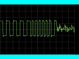
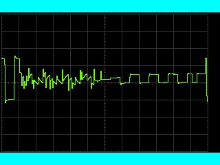
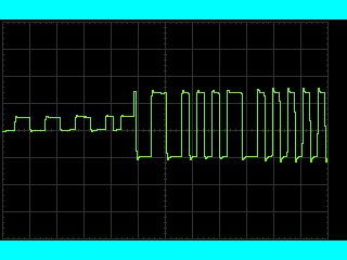
Here's some scope traces of a PSX-AR flipping phase. The three images overlap, so what you're seeing is one continuous event. If you're not familiar with the DCC signal or how an oscilloscope works, a very (very!) basic introduction is below. If you want to skip "the technical stuff" and just look at the pictures, have fun.

The technical stuff

An oscilloscope (scope) plots a graph of voltage vs time. (Don't doze off!) What's really cool about this is that it lets you see what a particular signal is doing. The center point is usually 0V, so anything above it is positive and anything below it is negative. Time goes left-to-right, with the left side being the oldest.

The DCC signal starts out with a pulse of a certain length and polarity, which is then immediately repeated at the same length but opposite polarity. The length of the pulse indicates either a 0 or 1 bit. (Zero stretching is accomplished by changing the length of the pulses at one polarity.)

The fun stuff

Before

This is the initial image. The DCC wave form usually looks something like the left-hand side of the image. In normal operation, the DCC signal is repeated on the other rail with opposite polarity. Note how the bit starts with negative polarity and is repeated with positive polarity here.

During

Here's what the PSX-AR output looked like while flipping. It would be interesting to see what it looks like with a better scope. The noise (really jaggy stuff) might be a result of toughing the alligator clip to the rail and pulling it away. The scope indicated that it took 2.18 ms to flip.

After

The final image shows the DCC signal on the right. Notice how the bit now begins with positive polarity and is repeated with negative polarity. It may look like the signal begins with negative polarity, but I suspect that's actually part of a bit that was missed. Confirmation could be done easily with a dual-channel scope.


DT400 battery voltage

Here's a handy little trick: On the Digitrax DT400-series throttle, you can insert a battery while looking at the screen. The screen will display the battery voltage as it powers on. The throttle must not be plugged in while doing this check.

9V non-rechargeable (Alkaline, heavy duty) batteries should be replaced when the voltage shown is under 8V.

I believe it works on the DT300-series throttles as well.


Tools, maybe a bit unusual

I took apart an old pool pump motor with worn out bearings. The bolts that held the motor together all broke off as I tried to remove them, so there was no way to save the motor. However, those bolts have made great stir rods. They're long enough to stir a container of plaster but not so long that they get in the way.

Another useful tool has been plastic spreaders. They were originally purchased for another project, but they've been quite useful for spreading out the plaster used for roads. Since they're plastic, they can be flexed a bit to give the road a crown in the center.

An ordinary kitchen sifter has been a very useful tool. The one I have is too coarse for most ground foam, but it works great for colored sawdust.

The final tool "discovery" is a multi-tool scraper blade. Multi-tools are relatively new on the market, and much has been said about them. They come with a variety of attachments, such as a half moon cutter, scraper, and more. When cutting foam, I usually used the cutters with the serrated edge to cut through the foam. However, the scraper does an excellent job of cutting foam with much less mess than the other cutters. There is a significant disadvantage, though: Noise. The vibration of the tool head creates a lot of noise while cutting the foam, especially if it isn't well secured.


View next 10 entries

Home Creative Stuff Model Railroad Ice Rink Computers message board Site Updates