Electrical2012-10-01 00:00:00
PSX-AR flipping polarity
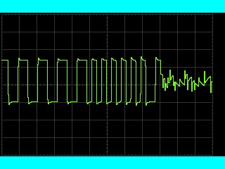
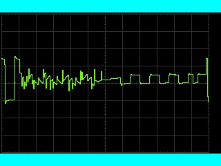
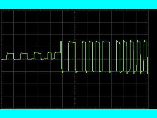
Here's some scope traces of a PSX-AR flipping phase. The three images overlap, so what you're seeing is one continuous event. If you're not familiar with the DCC signal or how an oscilloscope works, a very (very!) basic introduction is below. If you want to skip "the technical stuff" and just look at the pictures, have fun.The technical stuff
An oscilloscope (scope) plots a graph of voltage vs time. (Don't doze off!) What's really cool about this is that it lets you see what a particular signal is doing. The center point is usually 0V, so anything above it is positive and anything below it is negative. Time goes left-to-right, with the left side being the oldest.
The DCC signal starts out with a pulse of a certain length and polarity, which is then immediately repeated at the same length but opposite polarity. The length of the pulse indicates either a 0 or 1 bit. (Zero stretching is accomplished by changing the length of the pulses at one polarity.)
The fun stuff

This is the initial image. The DCC wave form usually looks something like the left-hand side of the image. In normal operation, the DCC signal is repeated on the other rail with opposite polarity. Note how the bit starts with negative polarity and is repeated with positive polarity here.

Here's what the PSX-AR output looked like while flipping. It would be interesting to see what it looks like with a better scope. The noise (really jaggy stuff) might be a result of toughing the alligator clip to the rail and pulling it away. The scope indicated that it took 2.18 ms to flip.

The final image shows the DCC signal on the right. Notice how the bit now begins with positive polarity and is repeated with negative polarity. It may look like the signal begins with negative polarity, but I suspect that's actually part of a bit that was missed. Confirmation could be done easily with a dual-channel scope.
