Log In Register


Puckdropper has scored 289 goals and 351 assists in his lifetime.


Twisting bus wires

Some areas of the layout have multiple wires running through them that look exactly the same as other wires but are for different purposes. Multiple main buses coming from a circuit panel would be such an example. If the wires run through holes with one wire per hole, keeping track of which wire belongs to what can be difficult.

Twisting the bus wires together provides not only an electrical benefit (as discussed on the Wiring for DCC website), but a physical benefit as well. Twisting bus wires together forms a cable, so any time you need to drop feeders to that bus you know that you've got the correct pair of wires.

This can make up for some deficiencies in a color code. An easy color code to use is color/black for track power, but in a complicated area multiple buses may have feeders dropped to them. If the wires are separate, it soon becomes easy to connect the track to the wrong black wire. Twisted, it's easier to keep track of.

There are some downsides to twisting, though. Twisted wires can make it harder to solder feeders to the bus, and some block detectors will detect false occupancy if twisted bus wires are used downstream from the detector.


Designing a panel

In a previous post, I mentioned a new panel will have more on it than I originally intended. Recently, I had the opportunity to design another panel and took a different route.

Panels are usually made up of components such as circuit breakers, autoreversers, distribution blocks, and internal wiring. The whole point of a panel is to route power from the distribution blocks via internal wiring to the circuit breakers and autoreversers. A good one will be easy to follow, while a bad one is just some stuff with wiring.

Input and outputs usually work best if they occur near (but not at) the edges of the panel. In some cases, it's necessary to run an input or output through the panel, but generally that's where the distribution wiring should be. If the panel will be installed in the middle of a section, be sure to leave space for multiple wires to be leaving at that point.

Lay out the distribution blocks first. This will give you a good idea where the power will come from to go to the components. With something like a PSX circuit breaker, the distribution block is the wires that connect via the Power Link terminals. Otherwise, a distribution block could be a terminal strip with wires that join multiple terminal lugs.

The circuit breakers and autoreverser can be laid out next. Consider where the input and outputs will be coming from. If the input is coming from the right, put the input connection on the right. Likewise, consider where the outputs will be. Laying out components then becomes the process of matching inputs and outputs.

Be sure to leave space around the components around for the wires. Wires need a certain amount of space to bend and flex to make a connection, so it's a good idea to leave a couple inches open around connectors. It may also be a good idea to cut the bus wires a little long in case the ends need to be cut and restripped.

With the components laid out and secured, it's time to handle the distribution wiring. Route each wire so that it is easy to follow. In the case where multiple wires travel together, try to avoid crossing wires. Take the time and use the extra wire needed to make this neat. Wires can be secured using staples.

If necessary, larger cable staples can be used to provide a path for bus wires to travel through the board. These need not be driven tight, they're just guides to keep the bus wiring separate from distribution wiring.

With the panel now designed and built, it's time to install. Good luck!


Quick Tip: Big jumps

Some DCC CVs have a valid range of 0-255. To determine the proper setting, increase the value by 20 or 32 instead of 1 or 2. When you get close, then change the value by smaller steps.


Hexadecimal Programming

While programs such as JMRI have abstracted many programming details away, there
are several places where it may be useful to look at the CVs directly and in
hex. Trying to use "normal numbers" or base-10 to program CVs may make things
harder than they have to be.

Some CVs such as CV29 can be thought of as a series of 8 on/off switches.
Programming these CVs in hex can be much easier than using decimal. If you want
to turn off bit 3, using decimal you have to subtract 8 or using hex all you
have to do is set the bit to zero and look up the new value.

8-bit hexadecimal can be thought of as two groups for 4 bits. The low nibble
contains the first 4 bits (0-3) and the high nibble contains the next 4 bits
(4-7). The two groups are side-by-side to complete the byte. 0100 0110 is
0x46.

Memorize this table:

Nibble Hex
0000 0
0001 1
0010 2
0011 3
0100 4
0101 5
0110 6
0111 7
1000 8
1001 9
1010 A
1011 B
1100 C
1101 D
1110 E
1111 F

The low bit (0 & 4) is the rightmost bit.

To change a bit, leave the others alone and change the appropriate value. Look
up the new result in the table.

To use Hexadecimal mode with the DT40x-series throttle during programming, set
the left-hand value to something other than an address and press the right knob
once. (It does not appear address programming can be done in hex.)


Quick Tip: Remove masking tape quickly

In building my scenery, I often use plaster of paris for the base. The track is already laid, so it has to be masked before applying the plaster. There's a lot of working time between applying the plaster and the time to remove the tape, but the time is not infinite. It may remove just fine the next day, but the cured plaster will prevent removal soon afterwards.


Interior Photos

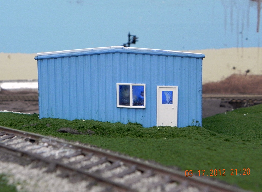
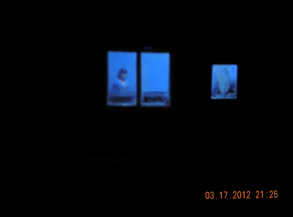
In the last couple of posts, lighting an office and adding an interior was discussed. Here are some photographs to show the results.

Office interior light in normal light.

\"Interior


Dremel attachment

I've used a variety of Dremel motor-tool attachments, and have found one that works really well for model railroad use. It's the 423E cloth polishing wheel. The wheel consists of several layers of cloth, which when combined with a proper polishing compound works well to get the crud off of wheels and track.

Before getting out the wire brush attachment, give this a try.


The Interior

As mentioned in my last real post, adding an interior to the lighted building was now a necessity. The building is in a very visible location on the layout, and looking into the office will be easy.

The hardest part about adding an interior is simply deciding what to put in it. Desk, file cabinets, pop machine, boxes, pallets, what kind of junk accumulates in an office of a warehouse? Rather than fully detailing the office, I added only four items: A table, a man with a briefcase, a woman, and white bear.

The floor was painted a grey color, with the same color used on the lower part of the wall as a chair rail. This may not be noticed, but it might help complete the scene.

Plastic glazing over the windows improves the look of the building while tending to obscure some of the details inside. This means that the items inside do not need to be A++ grade models, but only need to be C-grade models. The table, for example, leans a little and was quickly assembled, but I doubt anyone is going to notice.

Looking in the big window, you see the table, the lady looking at the direction of the bear in the corner, and the bear. The man was going to be visible through the glass on the door, but a small mishap with glue obscures him.

At night, with the room lights out a nice glow comes from the office windows. When you get close, the interior is visible and the effect is excellent.


Update to Version 1.0!

Version 1.0
-----------
1. Display of main posts are now CSS instead of tables.
2. Post a new message page UI redesigned.
3. Goals update page displays error messages correctly now.
4. Index page uses CSS completely
5. Added code to support version 0.8's lack of timezone identifier. PHP may still complain, but at least the code will run.
6. Updated SQL for version 1.0 updates; refactored update file to allow future updates to be easier.
7. The reset button on the post comment page has been removed.
8. Refactored category edit/delete page
9. Added comments_allowed field to install code
10. Refactored add admin page.
11. Updated, cleaned a bit, and refactored comment control pages.
12. Eliminated processing pages for forms.
13. Refactored unregistration page.
14. Removed API functions display_error_message and display_status_message
15. New API function: MessageBox(2-3)
16. The entire system has had a face lift. All pages now use CSS to enhance appearance. (The real reason to use CSS, eh?)
17. Broke up functions page (users shouldn't notice a thing).
18. Consolidated new post and edit post pages.
19. New Feature! HTML on individual main posts can be turned on and off.
20. Comments can be disabled on a per-post basis.
21. Commenting cut off date can be disabled on a per-post basis.
22. Colors and Options are now separate in the database.
23. The only reset buttons that remain are those on the options and color change pages.


Lighting an office

Adding light to a building demands a higher level of attention to the building. On the layout, the building will attract attention, especially if onlookers can see into the building. For this added detail, however, a certain price must be paid.

Light leaks through anywhere it can. The plastics used in many model kits tends to be translucent, especially if a light source is located near to the material. Gaps between corners and materials need to be sealed with a sufficiently light-proof coating to prevent light from getting out.

One method used to address the translucence issue was simply to paint the building, both inside and out. Several coats of paint will eventually build up and prevent light from passing through. A method I have not tried would be to line the building with an adhesive metal tape. If only doing one room, this might be an ideal solution.

Sealing gaps tended to be relatively easy because they were small. The building was intended to be lit from the beginning, so careful attention was paid to gaps to ensure they were as small as possible. In the case of this building, one gap was sealed by gluing a piece of styrene between the adjacent wall panels, while others were closed by using a gap-filling CA.

For the most recent building, only a small office in the much larger warehouse was being lit. The whole building was prepared to be lit, in case the office light leaked. It did. The office was lit with two small white LEDs through the ceiling.

When an LED lights, the entire thing glows and can put off considerable light. It may be necessary to mask the back and sides of the LED to reduce the amount of light escaping. One corner of the building leaked, but masking the LED reduced the excess light enough that no further work was necessary.

Now that the office has lights, it's quite easy to see that there's nothing in there. An interior seems to be a necessary next step....


View next 10 entries

Home Creative Stuff Model Railroad Ice Rink Computers message board Site Updates