Log In Register


Puckdropper has scored 283 goals and 341 assists in his lifetime.


PSX-AR flipping polarity

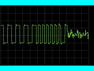
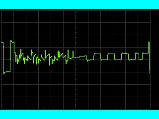
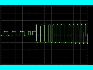
Here's some scope traces of a PSX-AR flipping phase. The three images overlap, so what you're seeing is one continuous event. If you're not familiar with the DCC signal or how an oscilloscope works, a very (very!) basic introduction is below. If you want to skip "the technical stuff" and just look at the pictures, have fun.

The technical stuff

An oscilloscope (scope) plots a graph of voltage vs time. (Don't doze off!) What's really cool about this is that it lets you see what a particular signal is doing. The center point is usually 0V, so anything above it is positive and anything below it is negative. Time goes left-to-right, with the left side being the oldest.

The DCC signal starts out with a pulse of a certain length and polarity, which is then immediately repeated at the same length but opposite polarity. The length of the pulse indicates either a 0 or 1 bit. (Zero stretching is accomplished by changing the length of the pulses at one polarity.)

The fun stuff

Before

This is the initial image. The DCC wave form usually looks something like the left-hand side of the image. In normal operation, the DCC signal is repeated on the other rail with opposite polarity. Note how the bit starts with negative polarity and is repeated with positive polarity here.

During

Here's what the PSX-AR output looked like while flipping. It would be interesting to see what it looks like with a better scope. The noise (really jaggy stuff) might be a result of toughing the alligator clip to the rail and pulling it away. The scope indicated that it took 2.18 ms to flip.

After

The final image shows the DCC signal on the right. Notice how the bit now begins with positive polarity and is repeated with negative polarity. It may look like the signal begins with negative polarity, but I suspect that's actually part of a bit that was missed. Confirmation could be done easily with a dual-channel scope.


DT400 battery voltage

Here's a handy little trick: On the Digitrax DT400-series throttle, you can insert a battery while looking at the screen. The screen will display the battery voltage as it powers on. The throttle must not be plugged in while doing this check.

9V non-rechargeable (Alkaline, heavy duty) batteries should be replaced when the voltage shown is under 8V.

I believe it works on the DT300-series throttles as well.


Tools, maybe a bit unusual

I took apart an old pool pump motor with worn out bearings. The bolts that held the motor together all broke off as I tried to remove them, so there was no way to save the motor. However, those bolts have made great stir rods. They're long enough to stir a container of plaster but not so long that they get in the way.

Another useful tool has been plastic spreaders. They were originally purchased for another project, but they've been quite useful for spreading out the plaster used for roads. Since they're plastic, they can be flexed a bit to give the road a crown in the center.

An ordinary kitchen sifter has been a very useful tool. The one I have is too coarse for most ground foam, but it works great for colored sawdust.

The final tool "discovery" is a multi-tool scraper blade. Multi-tools are relatively new on the market, and much has been said about them. They come with a variety of attachments, such as a half moon cutter, scraper, and more. When cutting foam, I usually used the cutters with the serrated edge to cut through the foam. However, the scraper does an excellent job of cutting foam with much less mess than the other cutters. There is a significant disadvantage, though: Noise. The vibration of the tool head creates a lot of noise while cutting the foam, especially if it isn't well secured.


350 feet by 700 feet isn't a lot of space

In the last post, we looked at an example of what would fit on a 4x8 cut into two pieces. One conclusion that may be drawn is that 4x8 isn't a lot of space. Another that can be drawn is that cutting a 4x8 in to two pieces is a stupid idea because it immediately eats half the space. In some cases, this second conclusion is wrong. In this post, we'll look at ways to increase the effective size of the layout without increasing the physical size.

Let's start with a backdrop. While a backdrop at 24" may seem like it immediately eats half the space, it actually creates a partition that allows the space to be better utilized. First, the average easy-reach distance is around 24-30". This means it's pointless to put track any farther from the edge of the layout than that, as model trains do derail and require handling. Second, and perhaps more important is that the backdrop creates a view block. Now, rather than seeing the entire layout at one time, the viewer can only see half of it. This allows something totally different to be on the other side. The train can easily and logically move from the heart of the city to the middle of a field without a sudden change in scenery.

Sometimes a backdrop isn't necessary to create a view block. It could be as simple as a building or a tree. Generally, anything that requires you to move to see the train at that point makes the layout feel bigger. How many times have you gone to watch a train and had a great view of the whole thing? Moving to get a better view is normal, and gives you a feeling of moving through the scenery.

While backdrops and view blocks can be very effective at making a layout feel bigger, they can also make it feel smaller. Breaking up a railroad in to too many segments can create a claustrophobic effect, where the scenery seems to end prematurely. Naturally, this situation must be avoided.

One thing that a backdrop does very well is emphasize the feeling that only a portion of a railroad is modeled. This means that tracks may begin and end at the edges and roads only need to go access industries, they don't need to actually reach their destination. It may be useful to imagine the track or roadway going beyond the layout edge, and what it does. For example, a road that continues off the edge might be a secondary road that connects to a highway that isn't modeled.

Naturally expanding from the previous suggestion is to make sure every track has a purpose. If the tracks all have a specific purpose, it's easy to name them and it follows that the railroad would have a purpose as well. Instead of dropping off a couple of cars "there", XYZW industries receives 2 boxcars. Perhaps the next day (or even later the same day), XYZW industries might have loaded the boxcars and is ready for them to be shipped to their destination. When operations begin, no matter how simple or disorganized, the collection of tracks stops being a train set and starts being a railroad.

A final suggestion for increasing the size of a tiny railroad requires a change in philosophy. Double track mainlines that run from division point to division point might sound appealing, but even large model railroads cannot hope to model all that. However, even a tiny railroad can support the traffic of a short line with several customers along the line. Trains can be any length, so the 3-4 car trains that a small layout supports are prototypical.

On shortlines, trackwork is often less than stellar, so track speeds are low. Track that supports 25 mph running would be typical of most layouts. At realistic track speeds, it should take well over 15 seconds for a train to cross an 8' module.

While these suggestions can make for a larger layout, they cannot be applied as a formula. Each part is a technique for increasing how large the layout feels, and can be done to excess with negative results.
Interpreting the chart

Last time, a simple chart was posted showing how things scale on a 4x8 layout. Perhaps the most important part of that chart was how big 4'x8' actually is. It's only 350' by 700', or about 5.6 acres. That's really not much. A large "Big Box" store and its parking lot could easily take up that amount of space. A 4x8 layout feels small because it is small.

Now this post isn't about bashing the 4x8 or complaining about how small it is for a model railroad, but to provide perspective on what will fit. Let's say you have a road going down the center of the layout. The track allows for a building to be placed approximately 4" from the edge of the layout, and the road overlaps the center of the layout by 1 1/2". This means there's 18 1/2" of space between the building and the road. What will fit?

A 30x50' building will certainly fit, and a semi would seem to fit as well. With the building oriented so the long side is parallel to the track, they only need about 13" of the space, right? Now for the important question: Is there enough room for the semi to work? There's 4 1/2" of space left, that's 32'. It's really tight, but it might work if semis can drive directly onto the road.

However, most roads have ditches along them, so better subtract another 11' (1 1/2") or so for them, and even more roads have entryways and driveways to keep things separated. In the normal case, that space cannot support a building and semi parked perpendicular to the building.

Angling the semi would save space, and a semi angled at 90 degrees would take up quite a bit less space. By orienting the semi with the long side of the layout, it may be possible to find the space required.

Let's take a look at this again. The road is in the same spot, as is the building. There is a ditch along the road, and a driveway oriented so the semi can pull away from its parking place at the building and turn on to the road. Instead of 18 1/2" of space available, there's now 13". The semi should have the ability to approach the road in such a manner that turning either direction is possible, so figure on needing space for that. If it takes 3/4" of the length of the semi for that, figure on needing 6.75" of space for that. There's now 5.25" left, or about 38' for the semi to turn towards the road. Looks like it will fit.

One more complication may present itself. What about utility poles? They're not going to be run in the ditch, do we need to adjust for them?

A final thought: At 60 miles per hour, a car is traveling 88 ft/sec. That means that a car traveling at highway speeds will traverse the length of the 4x8 in only 8 seconds.


Looking at a 4x8 with a little math

Just how big is the once ubiquitous 4' by 8' layout? As many layout builders have found out, not very. Let's take a look at how things scale out.

(Caution: technical paragraph.) Assuming HO scale, with a scale factor of 87.1:1, where 87.1' in scale equals 1' full size. Going from full size to scale is a matter of multiplying by 87.1, while going from scale to full size requires division by the same factor. Calculating the final column was done using the values in the "Actual" column. Calculated numbers are shown to 2 decimal places.

Description Actual Scale feet Scale inches Number to fill 4'
Layout width 348.4' 4' 48 n/a
Layout length 696.8' 8' 96 n/a
4x8 sheet of plywood4' x 8'.046' x .092' .55 x 1.1087.1, 43.55
Semi Truck 65' .75' 9 5.36
Average Boxcar 40' .46' 5.5 8.71
Single Road Lane 12' .14' 1.7 29
Two Lane Road 30' .34' 4.13 29
30x50 Building 30' x 50' .34' x .57' 4.13 x 6.9 11.61, 7
Golden Gate Bridge 6463.25' 75.29' 890.5 .054
1 Mile 5280' 60.7' 727.43 .065
Pitcher's mound to home plate See note 60.6' .70' 8.35 5.75

Note: 1 mile just happens to scale out to approximately the distance from the pitcher's mound to home plate.


Looking at the world upside down

I've been working on building a 4x8 layout that was designed on a computer. Laying things out on the first half of the layout has been only as hard as it had to be, but laying things out on the second half is quite a bit more confusing.

The problem is a view divider that goes down the back. The two halves of the layout are completely separate, in an attempt to make the layout feel bigger. However, the track plan ignores this distinction, so tracks that are on the right-hand side of the plan go on the left-hand side of the layout.

The easy solution, of course, is to turn the diagram upside down. However, when revising the plan on the computer it's impractical to work on the plan upside down. My method of dealing with it is to think about what track connects where, and to make the revisions accordingly. That is working out much better.


Opposite Switch

If you're laying out track to see how it fits, and find you need a switch that's a right hand but don't have one handy, you can use a left-hand switch of the same size. Just flip it over so the rails are down.


Lights

My layout has been designed with the intent of looking good at night. I've added details like streetlights, signals, and white LED headlights. Even some buildings are lit.

After shutting off the lights, though, the building gets quite dark. While the layout looks quite good, there's very little ambient light to see with. Turning on lights in the next room kinda works, but it doesn't look good.

My solution is rope lights. Menards has 48' of rope light for about $20. One strand has taken care of most of my layout, and another will give me plenty of excess. The lights come with clips for installation onto a wood surface, or zip ties for something like a iron railing. They're incandescent, so they do get warm.

Initially, I installed the rope lights on blocks mounted so the lights would be slightly underneath the edge of the fascia. This would allow light to shine from both the front and the bottom of the light. However, this turned out to be too bright. The effect created was one more of twilight and less of night. By moving the lights up, so light shines only out of the bottom, the aisles are well lit but the effect is night.

One of the few remaining issues now is that of light leaks. The fascia is not sealed against the foam on some pieces of the layout, so light leaks through. An old panel location has two large holes that are easily ignored in the daytime, but with the rope lights it's obvious where it was. To paraphrase Dr. Malcom in Jurassic Park, "[Light] breaks free, expands to new territories, and crashes through barriers, painfully, maybe even dangerously, but, ah, well, there it is." (Quote copied from http://www.imdb.com/title/tt0107290/quotes, except of course the word indicated with brackets.)

The rope lights install easily, look great, and provide a much needed improvement in safety. If (when?) I build another layout, I'll definitely install them again.


Puckdropper's Painting Rules

By now, I expect the basic rules of painting (don't paint yourself into a corner, clean your brush etc) are familiar to you. I've got a few to add based on either observation or experience.

1. Expect to get paint on you.

I always manage this somehow. It doesn't matter how careful I am, it still happens. All it takes is a little brush (pun unintended) with the paint.

2. When finished, leave the area.

I've painted things and tried to be careful as I kept working, but somehow rule #1 always finds a way. So, when finished, I always leave the area. Most paints need only a few hours to dry to the touch, so finding something else to do elsewhere isn't a big deal.

3. No drinks.

Observation or experience? You decide.

4. If the paint won't wash off your skin, don't panic.

It'll wear off in a few days. Until then, if anybody asks just tell them about your latest project. :-)


View next 10 entries

Home Creative Stuff Model Railroad Ice Rink Computers message board Site Updates